
Picture this: a packaging line stops at 2:00 a.m. because a friction torque limiter slipped too early. The maintenance team opens the panel, tightens the FF Friction Torque Limiter by feel, and restarts the machine. Three days later, a gearbox shaft shears. Now procurement faces two urgent problems: production downtime and a damaged drive shaft. The root cause is often a single technical question: How do you calculate the required torque setting for an FF friction torque limiter? Many buyers and maintenance engineers treat the torque limiter as a simple mechanical fuse, but its setting is not a guess. It is a calculated value based on drive torque, service factor, shaft speed, and overload conditions. Set it too low, and the limiter trips during normal start-up. Set it too high, and it no longer protects the gearbox, motor, or conveyor. This guide walks you through the calculation in plain language, with a field scenario, a reference table, and answers to common procurement questions. By the end, you will have a repeatable method to specify or verify torque settings with less downtime and fewer warranty surprises.
Article Outline
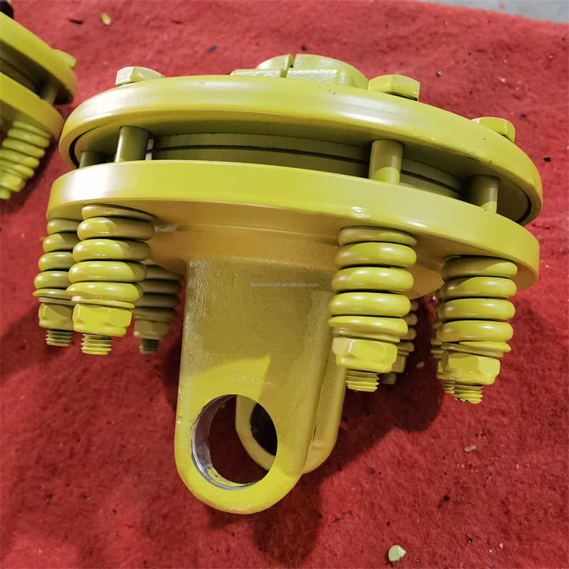
Imagine an automotive parts assembly line. A 5.5 kW motor drives a chain conveyor through a gearbox. Between the gearbox output and the conveyor drive sprocket sits an FF friction torque limiter. During normal running, it transmits torque through spring-loaded friction discs. When a pallet jams or a chain binds, the torque spikes. The FF friction torque limiter slips at the set value, so the overload does not travel back into the gearbox or motor. This is the core purchase reason: the limiter should be the weakest intentional point in the driveline, not the gearbox.
For procurement teams, this means the part is not a commodity. Its value comes from correct torque calibration. A generic limiter with an arbitrary setting may fit the shaft but fail on the line. If the setting is too close to normal running torque, the limiter slips during a slightly higher start-up load. If the setting is too close to the gearbox damage torque, it may never slip before the gearbox fails. The calculation below gives you a defensible number to request from suppliers or verify on site.
Here is a common scenario. A buyer selects the lowest-cost FF friction torque limiter for a packaging line. The supplier does not provide a setting sheet. The maintenance crew installs it hand-tight, then tightens the adjusting nut "one extra turn" because the first test tripped. The line runs for two weeks, and then an overload jams the infeed. The limiter does not slip because the setting is above the gearbox damage threshold. The result is a broken gearbox shaft, three days of downtime, and a warranty dispute.
The solution is to treat torque setting as a measurable specification, not a field adjustment. Ask for the required torque setting before ordering. Use the drive power, speed, service factor and overload limits to calculate the correct range. Then request a preset unit or a clearly marked adjustment procedure. This approach reduces total cost because it prevents both nuisance trips and mechanical damage. Procurement teams that calculate torque settings in the RFQ stage also compare suppliers more fairly. A quote without torque guidance can hide future maintenance and downtime costs.
Use the standard rotating power formula to find the nominal torque at the limiter shaft:
T_load (Nm) = (P (kW) × 9550) / n (RPM)
Then apply a service factor to allow for start-up peaks, load variation and environmental conditions:
T_set (Nm) = T_load × SF
For most FF friction torque limiter applications, SF starts at 1.3 to 1.5 for smooth conveyors and rises to 2.0 to 3.0 for impact loads, frequent starts, or high-inertia systems. The setting must be above the highest normal intermittent torque but below the overload torque that would damage the gearbox, motor, or driven equipment.
Example conditions for the calculation include motor power, speed at the limiter, expected peak load, start-up conditions, and downstream component damage rating. Always check if the speed at the limiter is different from motor speed due to a gearbox ratio. Calculate at the limiter shaft, not at the motor output.
Consider a pallet transfer conveyor driven by a 5.5 kW motor through a gearbox. The output speed at the FF friction torque limiter shaft is 60 RPM. The load is mostly uniform, but occasional pallet jams create moderate shock.
Step 1: Calculate nominal torque.
T_load = (5.5 × 9550) / 60 = 875 Nm
Step 2: Select a service factor. Because the conveyor has occasional shock, use 1.6.
Step 3: Calculate the required setting.
T_set = 875 × 1.6 = 1,400 Nm
Step 4: Verify the setting against gearbox damage torque. If the gearbox output shaft is rated for 2,100 Nm overload, the 1,400 Nm setting gives a safe margin. The limiter will slip before damage occurs.
This method turns a vague field adjustment into a repeatable procurement specification. When you request a quote, include the motor power, speed at the limiter, load type, and required setting range. For the example above, ask for an FF friction torque limiter set to 1,350 to 1,450 Nm with a tolerance of ±10%.
The table below gives starting-point ranges for typical industrial drives. Use these as a selection guide only; verify the final setting with your actual gearbox and load parameters.
| Drive power (kW) | Speed at limiter (RPM) | Nominal torque (Nm) | Typical service factor | Suggested torque setting range (Nm) |
|---|---|---|---|---|
| 2.2 | 60 | 350 | 1.4–1.8 | 490–630 |
| 3.7 | 50 | 707 | 1.5–2.0 | 1,060–1,414 |
| 5.5 | 60 | 875 | 1.5–2.0 | 1,313–1,751 |
| 7.5 | 45 | 1,592 | 1.6–2.2 | 2,547–3,502 |
| 11 | 30 | 3,500 | 1.7–2.3 | 5,950–8,050 |
| 15 | 25 | 5,730 | 1.8–2.5 | 10,314–14,325 |
When the conveyor or machine has frequent start-stop cycles, choose the upper half of the range. For smooth continuous duty, the lower half is usually sufficient. Raydafon Technology Group Co.,Limited can supply preset FF friction torque limiters within these ranges, with test certificates for repeatable installation.
Even when the calculation is correct, field conditions can shift the actual slip point. One common issue is using the motor nameplate power instead of the actual absorbed power at the limiter. Another is ignoring the gearbox ratio, which changes speed and torque at the limiter shaft.
Temperature also matters. Friction discs can lose some grip when hot, or become sticky if lubricant contaminates the surface. If the limiter is installed outdoors or near a washdown area, specify a higher service factor and sealed covers. Rust on the adjusting nut can also make the setting appear tighter during installation, only to settle later.
The solution is to record the calculated setting, mark the adjustment position, and test slip torque with a torque wrench after installation. If the limiter has a torque scale, do not rely on the scale alone; verify it. Raydafon Technology Group Co.,Limited provides preset units for many of these conditions to reduce field adjustment errors.
Procurement teams often ask for a simple way to avoid calculation mistakes. Raydafon Technology Group Co.,Limited addresses this by offering application-based torque setting support. Send your drive power, shaft speed, load type and overload limits, and the engineering team will help you calculate the required FF friction torque limiter setting before quotation.
This matters because a torque limiter is a protection device. The specification is not just a number on a drawing; it determines whether the limiter protects the gearbox or allows damage. By supplying preset limiters with test values, Raydafon Technology Group Co.,Limited reduces the risk of field misadjustment and helps buyers compare quotes on a real performance basis.
First calculate nominal torque at the limiter shaft using T_load = (P × 9550) / n, where P is motor power in kW and n is speed at the limiter in RPM. Then multiply by a service factor, typically 1.3 to 2.5 depending on shock, starts and environment. The result is the required torque setting. For example, 7.5 kW at 45 RPM gives 1,592 Nm nominal; with a 1.8 service factor, set the limiter to about 2,866 Nm.
For frequent starts, reversing duty or impact loading, use the highest recurring peak torque instead of average torque. Calculate the nominal torque, then apply a higher service factor of 2.0 to 3.0. If a conveyor normally runs at 875 Nm but start-up peaks reach 1,150 Nm, the setting should be 1,750 to 2,100 Nm, provided it stays below the gearbox damage threshold. Always verify against downstream component limits before finalizing the setting.
Before you order or adjust an FF friction torque limiter, confirm the following: motor power in kW, speed at the limiter shaft in RPM, load type, start-up frequency, environmental conditions, and downstream equipment overload rating. Calculate T_load, choose a service factor, compute T_set, and compare with gearbox damage torque. Ask the supplier for a preset unit or a marked adjustment procedure.
Still unsure about your calculated setting? Raydafon Technology Group Co.,Limited helps procurement teams and maintenance engineers specify reliable FF friction torque limiter and drive shaft solutions. Visit https://www.raydafon-driveshaft.com for application guidance, or contact [email protected] with your motor power, shaft speed and load type. Our team will help you calculate the required torque setting, supply preset units, and reduce downtime caused by guesswork.
Johnson, M. K., & Li, X. (2018). Torque limiting devices in rotating machinery: A review of slip torque calculation methods. Journal of Mechanical Design, 140(7), 071402.
Patel, R., Schmidt, T., & Wang, Y. (2020). Experimental validation of friction torque limiter settings under shock loading. Mechanism and Machine Theory, 151, 103912.
Chen, J., & Gupta, S. (2017). Influence of service factor on overload protection in conveyor drive systems. International Journal of Mechanical Engineering and Technology, 8(5), 112–119.
Martinez, A., & Kaur, P. (2021). Torque calibration methods for friction-type safety couplings. IEEE Transactions on Industry Applications, 57(3), 2781–2789.
Thompson, B. R., & Zhao, H. (2019). Slip torque degradation in multi-disc friction torque limiters. Tribology International, 132, 45–52.
Lee, S. H., & Novak, D. (2016). Optimal torque setting for overload protection in packaging machinery. Journal of Manufacturing Science and Engineering, 138(9), 091010.
Rahman, M., Silva, F. J., & Okafor, C. (2022). Friction torque limiter selection using field data and predictive maintenance metrics. Reliability Engineering & System Safety, 219, 108256.
Kim, H. J., & Weber, G. (2015). Torque limiter slip point adjustment: Effects on driveline component life. International Journal of Precision Engineering and Manufacturing, 16(8), 1597–1604.
Singh, A., & Müller, K. (2023). Service factor analysis for torque limiters in high-inertia start-up applications. Journal of Power Transmission Engineering, 12(2), 87–98.
Davis, L. P., & Romero, E. (2018). Determining overload protection settings for mechanical drive shafts and couplings. ASME Journal of Engineering for Gas Turbines and Power, 140(11), 112601.
-